Epson PowerLite 5000 Service Manual Page 44
- Page / 127
- Table of contents
- BOOKMARKS
- Service Manual 1
- PowerLite 5000 2
- VCCI COMPLIANCE STATEMENT 3
- REVISIONS 3
- COPYRIGHT INFORMATION 3
- TRADEMARK INFORMATION 3
- INTRODUCTION 4
- PRECAUTIONS 5
- Contents 7
- CHAPTER 4 TROUBLESHOOTING 9
- APPENDIX A 9
- 1.1 PRODUCT FEATURES 10
- 1.2 PARTS OF THE PROJECTOR 11
- Figure 1-3 12
- Figure 1-4 12
- Figure 1-5 13
- Figure 1-6 13
- Figure 1-8 14
- Figure 1-9 15
- 1.3 CONNECTIONS 16
- Power Book 18
- Table 1-1 18
- Video Devices 19
- Audio Devices 19
- 1.4 MAIN COMPONENTS 20
- FR board 21
- CN board 21
- Receptor boards 21
- Speakers 22
- Inlet unit 22
- Filter unit 22
- Power supply unit 23
- Lamp inner housing 23
- Control panel 23
- Optical engine 24
- Top side view 24
- Bottom side view 24
- 1.5 SPECIFICATIONS 25
- POWER SUPPLY 26
- 1.6 INTERFACE SPECIFICATIONS 27
- 1.6.5 S-Video 28
- 1.6.6 Video-In 29
- 1.6.7 Audio In L/R 29
- 1.6.8 Mouse / Com 1/2 30
- 2.1 HARDWARE 31
- Figure 2-2 33
- FC board 34
- Figure 2-3 34
- Figure 2-4 35
- 2.2 POWER SUPPLY UNIT 36
- Functional Outline 37
- Figure 2-7 38
- 2.3 MAIN BOARD 39
- • Lamp power 40
- • Backup Power 40
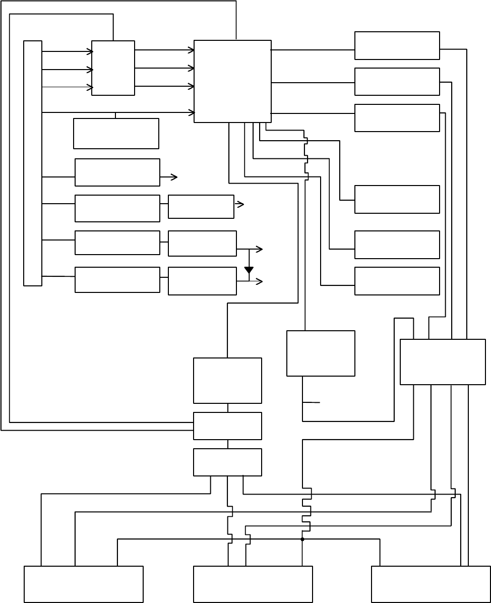
- 2.4 DRIVER BOARD 42
- Figure 2-11 44
- 2.5 CONTROL PANEL 45
- 2.6 AU BOARD 46
- 2.7 FR BOARD 48
- Figure 2-16 49
- 2.8 CN BOARD 50
- Figure 2-19 51
- Figure 2-20 51
- Figure 2-21 52
- 2.10 SPEAKER UNIT 53
- 2.11 LIGHT GUIDE BLOCK 54
- • Lens Arrays A and B 55
- 2.12 LAMP INNER HOUSING 56
- Light source lamp 57
- Fuse board (FU board) 58
- 2.13 SENSORS/SWITCHES 59
- 2.13.1 Filter Cover Switch 60
- 2.13.2 Interlock Switch 61
- 2.13.3 Safety Switch 61
- 2.13.5 LV Thermistor 62
- 2.13.4 Lamp Thermistor 62
- 2.13.6 PBS Thermistor 63
- 2.14 BOARD CONNECTIONS 64
- Figure 2-37 65
- Figure 2-38 65
- AC InIet 66
- Power Supply Connector 66
- Connector Board 66
- 3.1.1 Preparatory Procedures 67
- 3.1.4 Mechanical Adjustments 68
- Driver Board 69
- 3.1.6 Precautions 70
- Figure 3-1 71
- Figure 3-2 72
- Figure 3-3 72
- Figure 3-4 73
- Figure 3-5 74
- Figure 3-6 74
- Figure 3-7 75
- Figure 3-8 75
- Figure 3-9 76
- Figure 3-10 76
- Figure 3-11 77
- Figure 3-12 77
- Figure 3-13 78
- Figure 3-14 78
- Caution: 79
- 3.2.8 Removing the Main Board 80
- Figure 3-18 81
- 3.2.9 Removing the AU Board 82
- Figure 3-20 83
- Figure 3-21 84
- 3.2.11 Removing the FR Board 85
- Figure 3-24 86
- Figure 3-25 86
- Figure 3-26 87
- Figure 3-27 88
- Figure 3-28 88
- Figure 3-29 89
- Figure 3-30 90
- Figure 3-31 90
- Figure 3-32 91
- Figure 3-33 92
- Figure 3-34 92
- 3.2.20 Removing the CN Board 93
- Figure 3-37 94
- 3.2.22 Removing the FC Board 95
- Figure 4-1 97
- Figure 4-2 98
- Figure 4-3 99
- Power ON/OFF 100
- Continued from page 4-5 101
- Go to start 101
- Display/Picture 102
- Figure 4-7 103
- Audio Output 104
- Control Panel 105
- Remote Control 106
- Mouse/COM 107
- Figure 4-12 108
- A.1 Parts List 109
- A.2 Exploded Diagrams 112
- Figure A-2 113
- Figure A-3 114
- Figure A-4 115
- Figure A-5 116
- Figure A-6 117
- Figure A-7 118
- Figure A-8 119
- Figure A-10 120
- Figure A-11 121
- Figure A-12 122
- Figure A-13 123
- Figure A-14 124
- Figure A-15 126
- Figure A-16 127
Related products and manuals for Bridge cameras Epson PowerLite 5000
 (57 pages)
(140 pages)
(2 pages)
(224 pages)
(57 pages)
(140 pages)
(2 pages)
(224 pages)
© 2020, manymanuals.com. All rights reserved. | 0.317 s |
 Manymanuals.com
 Manymanuals.de
 Manymanuals.fr
 Manymanuals.it
 Manymanuals.pl
 Manymanuals.cz
 Manymanuals.es
 Manymanuals-pt.com
Comments to this Manuals