Epson Stylus Pro XL Service Manual
Browse online or download Service Manual for Print & Scan Epson Stylus Pro XL. Epson Stylus Pro XL Service manual User Manual
- Page / 127
- Table of contents
- TROUBLESHOOTING
- BOOKMARKS
- SERVICE MANUAL 1
- Chapter 1 Product Description 2
- 1.1 FEATURES 4
- Table 1-1. Interface Cards 5
- 1.2 SPECIFICATIONS 6
- Table 1-3. Character Tables 7
- 1.2.3 Paper Specifications 8
- Printable area: Cut sheets 9
- Envelopes 9
- 1-6 Rev.A 9
- Cut Sheets Envelopes 10
- Carriage Unit 10
- : Without condensation 11
- 1.2.7 Reliability 12
- 1.2.8 Safety Approvals 12
- 1.2.9 Physical Specifications 12
- 1.3 INTERFACE SPECIFICATIONS 13
- 1.4 OPERATIONS 16
- Indicators 17
- 1.4.3 Default Settings 18
- 1.4.3.1 Default Setting Items 18
- Table 1-17. Feature Selection 19
- Operate LED Data LED 20
- 1.4.4 Error Conditions 21
- Table 1-19. Error Indications 21
- 1.4.5 Printer Initialization 21
- 1.5 MAIN COMPONENTS 22
- 1.5.5 Housing 24
- Table of Contents 25
- List of Figures 26
- List of Tables 26
- 2.1 OVERVIEW 27
- 2.2.1 Printer Mechanism 28
- Micro Dot Printing mode 30
- CR Motor 31
- CR HP Sensor 31
- Carriage Guide Shaft 31
- Belt Pulley 31
- 2.2.3 Paper Feed Mechanism 32
- Table 2-5. Drive Terms 33
- 2.2.4 Ink System 34
- Drive: Pump Mechanism 35
- Drive: Switch Lever Set 35
- Drive: Paper Feed Mechanism 36
- Switch Lever: Reset 36
- Figure 2-12. Pump Operation 37
- 2.2.7 Wiping Mechanism 38
- 2.3.2.1 Reset Circuits 42
- 2.3.2.2 Sensor Circuits 42
- STROBE pulse 44
- 2-18 REV.-A 44
- Normal Dot Mode 46
- Drive Waveform 46
- Micro Dot Mode 46
- Block Resistor 46
- Micro Dot Printing Mode 47
- 2.3.2.6 DMA Controller 48
- CPU H8 (IC1) DRAM (IC5) 49
- 2.4 INK SYSTEM MANAGEMENT 50
- 2.4.1 Ink Operations 51
- 2.4.2.1 Protect Counter 53
- 3.1 OVERVIEW 56
- ATTENTION 56
- 3-2 REV.-A 57
- DISASSEMBLY/ASSEMBLY POINT 58
- C137 PNL Board 58
- Carriage Lock Lever 58
- CBB (M3x11) 58
- CBS (M3x8) 59
- C162 MAIN Board 59
- CBB (M3x12) 59
- ASSEMBLY POINT 61
- REQUIRED ADJUSTMENT 61
- Ink Cartridge 63
- Fixing Lever 63
- Cartridge Holder 63
- Figure 3-9. Printhead Removal 64
- 3.2.5.2 Carriage Unit Removal 67
- 3.2.5.3 Pump Unit Removal 68
- Cleaner Lever 69
- 3.2.5.5 CR Motor Removal 70
- 3.2.5.6 PF Motor Removal 70
- 3.2.5.8 PE Sensor Removal 71
- Paper Feed Roller 72
- 3.2.5.10 Upper Frame Removal 73
- Chapter 4 Adjustments 74
- 4.1 OVERVIEW 75
- Adjustments Stylus Pro XL 76
- Stylus Pro XL Adjustments 77
- Head Base 79
- Figure 4-5. Spacer Selection 80
- Spacer Name 87
- Thickness 87
- Figure 4-15. Spacer Selection 87
- 4.1.7 Platen Gap Adjustment 90
- Chapter 5 Troubleshooting 92
- Rev.-A 5-i 93
- 5.1 OVERVIEW 94
- Table 5-3. Error Codes 95
- 5.2.2 Error is detected 98
- Stylus Pro XL Troubleshooting 100
- Troubleshooting Stylus Pro XL 101
- Chapter 6 Maintenance 108
- 6.1 PREVENTIVE MAINTENANCE 109
- 6.2 SERVICE MAINTENANCE 110
- 6.3 LUBRICATION AND ADHESIVES 111
- 6-4 Rev.A 112
- Rev.A 6-5 113
- 6-6 Rev.A 114
- Appendix 115
- A.1 CONNECTOR SUMMARY 116
- Table A-1. Connector Summary 117
- Stylus Pro XL Appendix 118
- Appendix Stylus Pro XL 119
Summary of Contents
EPSON COLOR INKJET PRINTERStylus Pro XLSERVICE MANUALEPSON4004677
Setting theadjust lever: The adjust lever on the carriage unit must be set to the proper position forthe paper thickness, as shown in Table 1-6.Table
5.2.4 Printer does not feed the paper correctly.STARTENDENDYESYESNONOYESYESNONOYESNOIs paper loadedin the sheet feedercorrectly?Load the papercorrectl
5.2.5 Control panel operation is abnormal.STARTENDYESYESNONOENDYESNOConnect the controlpanel correctly.Replace the control panel.Replace the C162MAIN
5.3 UNIT REPAIR - C137 PSB/PSE BOARDThis section describes problems related to the power supply board (C137 PSB/PSE). The tablebelow provides various
5.4 UNIT REPAIR - C162 MAIN BOARDThis section describes the problems related to the main controller board (C162 MAIN). The tablebelow provides various
Table 5-6. Repair of the C162 MAIN (Cont.)Symptom Condition Cause Checkpoint SolutionCarriagedoes notoperatenormally.The carriagedoes notoperate at al
5.5 UNIT REPAIR - PRINTER MECHANISM (M-4A60)Any problems related to the printer mechanism should be repaired according to thetroubleshooting procedure
Table 5-8. Repair of the Printer Mechanism (Continued)Symptom Condition Cause Checkpoint SolutionPrinting isnotperformed.The carriagemoves, but nopri
Table 5-7. Repair of the Printer Mechanism (Cont.)Symptom Condition Cause Checkpoint SolutionPaper is notfed normally.Paper is not fed.Foreignsubstanc
Chapter 6 MaintenanceTable of Contents6.1 PREVENTIVE MAINTENANCE 6-16.2 SERVICE MAINTENANCE 6-26.2.1 PrintheadCleaning...
6.1 PREVENTIVE MAINTENANCEAlthough this printer is designed so that no specific maintenance is required on a regular basis, it isrecommended that yo
1.2.5 Electrical SpecificationsTable 1-7. Rated Electrical RangesSpecification 120 V Version 220 - 240 V VersionRated voltage 120 VAC 220 - 240 VACInp
6.2 SERVICE MAINTENANCECertain maintenance is required when the printer detects an error or when a decline in print quality isobserved.6.2.1 Printhead
6.3 LUBRICATION AND ADHESIVESThe printer must be lubricated properly when it is disassembled for component replacement, or if mechanicalnoise exceeds
❒ Do not apply too much lubricant, as it may stain the mechanism as well as a cause amechanism malfunction.Maintenance Stylus Pro Service Manual6-4
211717223021279874465111220Figure 6-1. Lubrication Points and Adhesive Points (1)Stylus Pro Service Manual MaintenanceRev.A 6-5
16(3)19181814142810311221122Lubrication PointAdhesive PointFigure 6-2. Lubrication Points and Adhesive Points (2)Maintenance Stylus Pro Service Manual
AppendixTable of ContentsA.1 CONNECTOR SUMMARY A-1A.2 CIRCUIT DIAGRAM A-7A.3 CIRCUIT BOARD COMPONENT LAYOUT A-14A.4 EXPLODED DIAGRAM A-18List of Figur
A.1 CONNECTOR SUMMARYThe figure below shows the interconnection between the major components of the Stylus Pro XL.CN1CN2C137 PSB/PSEC137 PNLC162 MAINC
Table A-1. Connector SummaryBoard Location Pin DescriptionC162 MAINCN1 36Centronics parallel I/FCN2 36Type B parallel I/FCN3 8RS-422 serial I/FCN4 —Th
Table A-3. Connector Pin Assignments — CN2Pin I/O Name Description1-6I+5 V Power supply for I/F drive7OTXD Transmit data8OREADYReady signal9IRXD Recei
Table A-6. Connector Pin Assignments — CN6Pin I/O Name Description1OCRA Phase A drive signal2OCRAPhaseA drive signal3OCRB Phase B drive signal4OCRBPha
1.2.7 ReliabilityTotal print volume: 75,000 pages (A4, letter)Printhead life: 1,000 million dots/nozzle1.2.8 Safety ApprovalsSafety standards: 120 V v
Table A-11. Connector Pin Assignments — CN11Pin I/O Name Description1—GND Ground2OBCLK Clock signal for black head3—GND Ground4OBLAT Latch signal for
Table A-14. Part No. Reference TableRef.No. Description PPL Name100LOWER HOUSING HOUSING, LOWER101FOOT FOOT102LOWER SHIELD PLATE SHIELD PLATE, LOWER10
Table A-14. Part No. Reference Table (Continued)Ref.No. Description PPL Name200 MAIN BOARD (FOR USA, S.E. ASIA)BOARD ASSY., MAIN(FOR USA, S.E. ASIA)20
Table A-14. Part No. Reference Table (Continued)Ref.No. Description PPL Name520REAR PAPER GUIDE PAPER GUIDE ASSY., REAR521PF ROLLER SUPPORT ROLLER, PF
Table A-14. Part No. Reference Table (Continued)Ref.No. Description PPL Name561BK HEAD BASE BASE, HEAD, BK562YMC HEAD BASE BASE, HEAD, YMC563UPPER HEA
Table A-14. Part No. Reference Table (Continued)Ref.No. Description PPL Name603EXTENTION SPRING, 1.6 g EXTENTION SPRING, 1.6604COMPRESSION SPRING, 90
Table A-14. Part No. Reference Table (Continued)Ref.No. Description PPL Name650CBB SCREW (M3×12) C.B.B. SCREW (M3×12)652CBS SCREW (M3×8 F/UC) C.B.S. S
1.3 INTERFACE SPECIFICATIONSThe Stylus Pro XL is standard-equipped with an 8-bit parallel and serial interface.1.3.1 Parallel Interface Specifications
Table 1-9 shows the connector pin assignments and signal functions of the 8-bit parallel interface.Table 1-9. Signal and Connector Pin Assignments for
1.3.2 Serial Interface SpecificationsData format: RS-422 serialSynchronization: AsynchronousHandshaking: By DTR signal and X-ON/X-OFF protocolTable 1-
1.4 OPERATIONSThis section describes the basic operations of the printer.1.4.1 Control PanelThe control panel for this printer has 1 lock-type, 5 non-
IndicatorsOperateOn when the printer is on. Blinks during power on and off sequence.Data On when print data is in the input buffer. Data and Pause lig
1.4.3 Default SettingsThe printer can save some printer setting parameters that define its functions at initialization. You canchange these parameters
1.4.3.2 Changing the Default SettingsTo change the printer’s default settings:1.Hold down the Economy/Condensed button and turn on the printer. The pr
Chapter 1 Product DescriptionTable of Contents1.1 FEATURES 1-11.2 SPECIFICATIONS 1-31.2.1 PrintingSpecifications...
Table 1-18. Character Table SelectionVersionSettingsOperate LED Data LEDPaper OutLEDCommonItalic U.S.A.OffOff Off^Italic FranceOnOff Off^Italic German
1.4.4 Error ConditionsThe printer can detect various errors and indicate them with LEDs.Table 1-19. Error IndicationsErrorData LEDPaper OutLEDNo InkCa
1.5 MAIN COMPONENTSThe main components of the Stylus Pro XL are:❏ Printer mechanism (M-4A60)❏ Main control board (C162 MAIN Board)❏ Power supply unit
1.5.2 Power Supply Board (C137 PSB/PSE Board)The power supply board (C137 PSB/PSE Board) consists of an RCC switching regulator circuit. This board is
1.5.4 Printer Mechanism (M-4A60)The M-4A60 printer mechanism is equipped with a 64-nozzle black printhead and 48-nozzle color (CMY)printhead on the ca
Chapter 2 Operating PrinciplesTable of Contents2.1 OVERVIEW 2-12.2 OPERATING PRINCIPLES OF THE PRINTER MECHANISM 2-12.2.1 PrinterMechanism...
List of FiguresFigure2-1. PrinterMechanismBlock... 2-1Figure2-2. StructureofPrinthead...
2.1 OVERVIEWThis section describes the operating principles of the printer mechanism and the electrical circuitsof the Stylus Pro XL.2.2 OPERATING PRI
2.2.1 Printer MechanismThe printer mechanism of this printer uses a drop-on-demand ink jet system similar to the systemused on all other EPSON ink jet
Principles of the Printing OperationThe printhead operates in one of two modes to eject ink from each nozzle:❏ Normal stateNo electrical charge is app
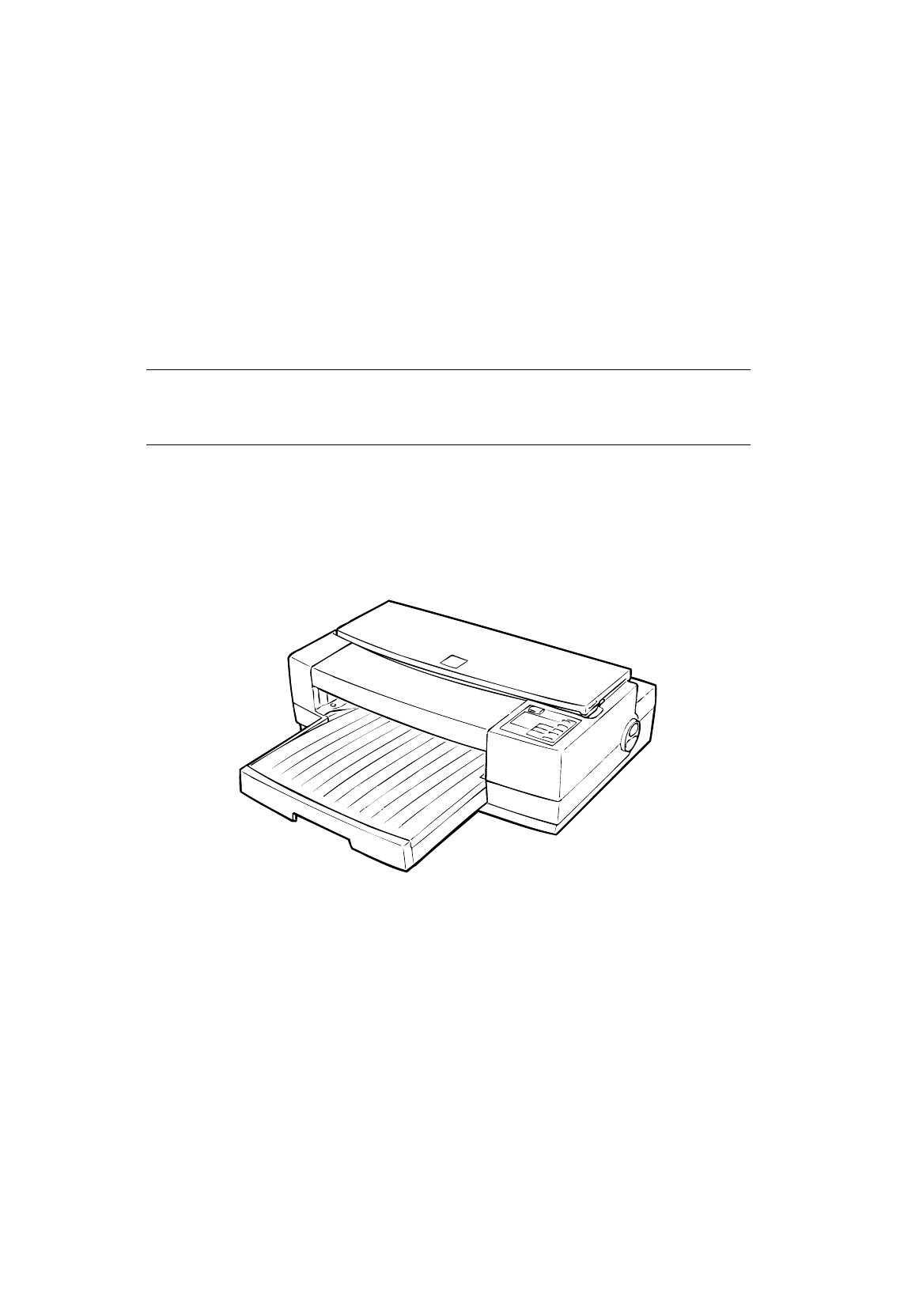
List of FiguresFigure 1-1. Exterior View of the Stylus Pro XLFigure 1-2. Nozzle ConfigurationFigure 1-3. Printable Area for Cut SheetFigure 1-4. Print
Micro Dot Printing modeThe Stylus Pro XL printer has a special printing mode, called “Micro Dot Printing mode”. Thisprinting mode can be selected by a
2.2.2 Carriage Drive MechanismThe timing belt attached to the base of the carriage unit is driven by the carriage motor, causing thecarriage unit to m
2.2.2.1 Platen Gap Adjust LeverThe platen gap adjust lever, which is attached to the carriage unit, needs to be set to an appropriateposition for the
Table 2-5. Drive TermsModeFrequency(pps)Current Value (mA)Acceleration/DecelerationConstant Rush HoldPaper loading 1600 970/750 750 750 240ASF feed 16
2.2.4 Ink SystemThis printer’s ink system is composed of the following mechanisms:❏ Ink cartridge❏ Pump mechanism❏ Cap mechanism❏ Waste ink drain tank
2.2.5 Pump MechanismThe paper feed motor drives the pump mechanism when the transmission gear is moved to theposition where the paper feed motor engag
Drive: Paper Feed MechanismSwitch Lever: ResetCarriageFigure 2-10. Paper Feed Mechanism Block DiagramCarriageD/E Reset LeverD/E LeverFigure 2-11. Swit
Table 2-6. Pump Mechanism OperationPF Motor Rotational Direction OperationClockwise (CW)forward rotation❏Color absorption❏Color micro absorption❏Color
2.2.6 Cap MechanismThe cap mechanism prevents the printhead nozzles from drying and keeps bubbles from forminginside the nozzle while the printer is n
2.3 OPERATING PRINCIPLES OF THE ELECTRICAL CIRCUITSThe Stylus Pro XL contains the following circuit board units:❏ C162 MAIN Board (main control circui
1.1 FEATURESThe Stylus Pro XL is a 64 + 48-nozzle (monochrome and CMY) color ink jet dot matrix printer.The major features of this printer are:❏ High-
The figure below shows a block diagram of the power supply circuit (C137 PSB/PSE). The powerswitch is equipped with a secondary circuit that allows th
2.3.2 Operating Principles of the Main Control CircuitThe main control circuit of this printer is the C162 MAIN Board. This circuit is controlled by t
2.3.2.1 Reset CircuitsThe C162 MAIN Board contains 2 reset circuits: the +5 V monitor reset circuit and the +35 Vmonitor reset circuit. The +5 V monit
2.3.2.3 Carriage Motor Drive CircuitThe carriage motor drive IC SLA7041MS (IC15) outputs a constant current to drive the carriagemotor for the printer
The following figure shows the contents of the four-bit serial data and how this data transactswith the SLA7041MS driver. The step time of the referen
2.3.2.4 Paper Feed Motor Drive CircuitThe paper feed motor for this printer drives the following mechanisms:❏ Paper feed mechanism❏ Paper pickup mecha
2.3.2.5 Printhead Drive CircuitThe printhead drive circuit for this printer is composed of the following two parts:❏ Common drive circuit (trapezoidal
Micro Dot Printing ModeThe Stylus Pro XL printer has a special printing mode, called “Micro Dot Printing Mode.” Thisprinting mode can be selected by c
2.3.2.6 DMA ControllerData from the host computer is received automatically by the STB signal via the external Centronicsinterface. The data is input
2.3.2.7 DRAM Refresh ControllerThe H8 CPU is equipped with a refresh controller in the internal controller. This CPU can contactthe 16-bit-long IC5 DR
Table 1-1. Interface CardsInterface Card Model NumberSerial interface card C823051/C82306132KB serial interface card C823071/C82308132KB parallel inte
2.4 INK SYSTEM MANAGEMENTThis section explains how the ink system is controlled to protect the printhead and ink supplysystem and to ensure high-quali
2.4.1 Ink OperationsVarious ink operations can be performed selectively by the printer.1 Power On OperationThis operation is performed when power is t
14 Disengage Off OperationThis operation resets the switch lever to the position where it transmits the PF motor drive to thepump mechanism. It also m
2.4.2 Timer and CounterEEPROM LE93C46 (IC12) on the main board stores certain counter and timer values used forcontrolling ink system operation.2.4.2.
Chapter 3 Disassembly and AssemblyTable of Contents3.1 OVERVIEW 3-13.1.1 PrecautionsforDisassemblingthePrinter...3-13.2 DISASSEM
List of FiguresFigure3-1. DisassemblyFlowchart... 3-2Figure3-2. C137PNLControlPanelRemoval... 3-3
3.1 OVERVIEWThis section describes procedures for disassembling the main components of this printer. Unlessotherwise specified, disassembled units or
3.2 DISASSEMBLY AND ASSEMBLYWARNINGFollow the precautions in Section 3.1.1 when disassembling the printer.This section consists of the subheads shown
3.2.1 Upper Case Removal1.1. Remove the printer cover (center of top) by releasing the 2 tabs holding it to the upper case.2. Remove the front cover (
3.2.2 Power Supply Unit (C137 PSB/PSE Board) Removal1. Remove the upper case (see Section 3.2.1).2. Disconnect the cables from connectors CN1 on the C
1.2 SPECIFICATIONSThis section provides statistics and other detailed information for the printer.1.2.1 Printing SpecificationsPrint system: On demand
3.2.3 Main Controller (C162 MAIN Board) Removal1. Remove the upper case (see Section 3.2.1).2. Remove the grounding plate from the shield plate.3.Remo
ASSEMBLY POINT❏ When you replace the main board, initialize EEPROM contents as follows:1. Reassemble the printer.2. Turn the printer on while holding
3.2.4 Printer Mechanism (M-4A10) Removal1. Remove the upper case (see Section 3.2.1).2. Remove the power supply unit (see Section 3.2.2).3. Remove the
3.2.5 Printer Mechanism DisassemblyThe procedures described in this section explain how to remove the components within theprinter mechanism.3.2.5.1 P
6.Remove the CBB (M3×11) screw (under the CR cap cover) and plain washer securing themonochrome and color printheads to the carriage base.7 Pull the b
CAUTION❏ Take proper measures to protect the printhead unit from static electricity, because thedriver IC is directly attached to the printhead unit.❏
REQUIRED ADJUSTMENT❏ When removing or changing the black head, the following adjustments are needed.1. Black head angle adjustment (see Section 4.1.4)
3.2.5.2 Carriage Unit Removal1. Remove the printer mechanism (see Section 3.2.4).2. Move the carriage to the left side of the printer while pressing t
3.2.5.3 Pump Unit Removal1. Remove the printer mechanism. (See Section 3.2.4.)2. Remove the carriage unit. (See Section 3.2.5.2.)3. Remove the CBS (M3
3.2.5.4 Cleaner Head Replacement1. Remove the printer mechanism (see Section 3.2.4).2. Use tweezers to unhook the cleaner head from the hook on the cl
Character sets: Legal and 14 international character sets.Character tables: See Table 1-3.Table 1-3. Character TablesBit map font Scalable fontCharact
3.2.5.5 CR Motor Removal1. Remove the printer mechanism (see Section 3.2.4).2. Release the timing belt (see section 3.2.5.2).3. Remove the 3 screws se
3.2.5.7 Carriage Home Position Sensor Removal1. Remove the printer mechanism. (See Section 3.2.4.)2. Disconnect the sensor cable from the carriage hom
3.2.5.9 Paper Feed Roller Assembly Removal1. Remove the printer mechanism (see Section 3.2.4).2. Remove the carriage unit (see Section 3.2.5.2).3. Rem
3.2.5.10 Upper Frame Removal1. Remove the printer mechanism (see Section 3.2.4).2. Remove the carriage unit (see Section 3.2.5.2).3. Remove the E-ring
Chapter 4 AdjustmentsTable of Contents4.1 OVERVIEW 4-14.1.1 DestinationDataWritingOperation...4-24.1.2 Bi-D(BidirectionalPr
4.1 OVERVIEWThis section describes adjustments required when the printer is disassembled and assembled afterrepair. Since this printer has both a blac
4.1.1 Destination Data Writing OperationThe setup value that specifies the printer destination is stored in the EEPROM on the C162 MAINboard. Therefor
4.1.2 Bi-D (Bidirectional Printing) Alignment AdjustmentThe bidirectional alignment is required when the printer mechanism, main board, or printhead(b
4.1.3 Head Gap Adjustment (Black and Color Head)The head gap adjustment is required when the printer mechanism, main board, or printhead(board) is rep
4.1.4 Black Head Angle AdjustmentThe black head angle adjustment is required when the black head is replaced or disassembled. Ifthis adjustment is not
1.2.2 Paper Handling SpecificationsFeeding method: Friction feed paper is fed from the built-in auto sheet feeder (ASF).Notes: The following operation
1. Connect the PC to the target printer, and turn the printer on.2. Execute BASIC on the PC and run the program “VERxxx.BAS.”1. Destination Setting2.
7. Turn the printer power off now.8. Manually move the carriage to the center while pressing the carriage lock lever, and removethe two ink cartridges
11. After replacing the angular spacer, reassemble the ink cartridge holder and reinstall the inkcartridges. Use the BASIC program to verify the angle
4.1.5 Black - Color Head Vertical AdjustmentThis adjustment calibrates the vertical position between the black head and the color head. Alignthe top n
4. In Figure 4-10, the vertical position is correct when both the magenta line and the black lineare aligned (as shown in position OK (0)). If the ver
8. Change the linear spacers (2 spacers for the monochrome head only) with new ones, referringthe figure below. (Replace linear spacers using tweezers
4.1.6 Color Head Angle AdjustmentThe color head angle adjustment is required when the color head is replaced or disassembled.If this adjustment is not
Angular spacers for the color head come in five thicknesses, each having its own shape. Thefollowing figure shows the relationship between the shape a
7.Remove the rubber cap covering the head screw at one side of color ink cartridge. Then loosen(but do not remove) 3 screws. (Refer to the figure belo
9. Rerun the BASIC program and choose “Head Angle Confirmation Pattern” again by typing 2and ENTER. Then verify that the confirmation sample is correc
Printable area: Cut sheetsEnvelopesNotes: A:Theminimumtopmargin=3mm(0.12in.)B: The minimum left margin = 3 mm (0.12 in.)C:The minimum right margin is:
4.1.7 Platen Gap AdjustmentThis adjustment is required when the carriage unit is replaced or removed from the printermechanism. Adjust the distance be
6. Move the carriage manually to the right adjustment position and repeat steps 3 and 4,referring to Figures 4-18 and 4-19.4.1.8 Internal Timer Reset
Chapter 5 TroubleshootingTable of Contents5.1 OVERVIEW 5-15.2 UNIT LEVEL TROUBLESHOOTING 5-35.2.1 Printer Does Not Operate at Power on. . . . . . .
Rev.-A 5-i
5.1 OVERVIEWThe printer may exhibit different symptoms for the same problem, which makes troubleshootingmore difficult. However, this section provides
Table 5-3. Error CodesErrorStatusLEDRecoveryDataPaperOutNo InkCartridgeEconomy Condensed PausePaper out On OnLoad paper in thetray, press Load/Eject,
5.2 UNIT LEVEL TROUBLESHOOTINGWhen a problem occurs, you can identify the defective unit based on the symptoms exhibited. Thetable below lists the sym
5.2.1 Printer does not operate at power on.STARTENDYESNOYESNOYESNOYESNOYESNO Is the AC input voltage correct? Use the correctinput voltage. Has fuse(
5.2.2 Error is detected.STARTENDENDYESYESYESYESNONONONOYESNOIdentify the typeof error indicated.(See Table 5-3.)Carriage errorTurn the printer off and
5.2.3 Failure occurs during printing.Replace the C162MAIN board.STARTENDENDYESYESYESNONONOYESYESYESNONONORun the self-test . Connect the cablescorrect
More documents for Print & Scan Epson Stylus Pro XL


Related products and manuals for Print & Scan Epson Stylus Pro XL
 (137 pages)
(24 pages)
(6 pages)
(137 pages)
(24 pages)
(6 pages)


 (20 pages)
(23 pages)
(20 pages)
(23 pages)
 (142 pages)
(17 pages)
(6 pages)
(6 pages)
(123 pages)
(7 pages)
(213 pages)
(12 pages)
(142 pages)
(17 pages)
(6 pages)
(6 pages)
(123 pages)
(7 pages)
(213 pages)
(12 pages)
 (203 pages)
© 2020, manymanuals.com. All rights reserved. | 1.851 s |
 Manymanuals.com
 Manymanuals.de
 Manymanuals.fr
 Manymanuals.it
 Manymanuals.pl
 Manymanuals.cz
 Manymanuals.es
 Manymanuals-pt.com
Comments to this Manuals