Epson 7500 User Manual
Browse online or download User Manual for Printers Epson 7500. Epson 7500 User Manual
- Page / 58
- Table of contents
- BOOKMARKS
- Setup Guide 1
- Important Safety Instructions 5
- Instructions Importantes de 7
- Skuriti! 7
- Contents 9
- Introduction 11
- Chapter 1 12
- Choosing a Location 13
- Removing the Protective Card 14
- Connecting a Monitor 15
- Using the Parallel Port 18
- Using the Serial Ports 20
- Connecting the Keyboard 21
- Connecting the Mouse 22
- Connecting the Power Cord 24
- Turning On the Computer 25
- Where To Go Next 26
- Chapter 27
- Starting the SETUP Program 28
- Setup function keys 29
- [Alt]pi--J 29
- Setting the Date and Time 30
- Setting the Diskette Drive(s) 30
- Video display type options 31
- Self test error levels 32
- Running the SETUP Program 32
- Setting the Cache 33
- Cache options 33
- Setting the Shadow RAM 33
- Shadow RAM options 34
- Valid shadowing options 34
- Security options 35
- Hard Disk Drive Types 38
- Defining Your Own Drive Type 40
- Drive type options 40
- Checking System Memory 41
- Setting the Booting Sequence 41
- Setting the Virus Warning 42
- NumLock Boot Status 43
- On or Off 43
- NumLock Boot 43
- Bus control options 44
- I/O control options 45
- Cache/DRAM control options 47
- PRESS F5 TO SAVE AND EXIT 48
- PRESS F1 TO EXIT W/O SAVE 48
- Post-SETUP Procedures 49
- Using Memory 50
- Types of Memory 50
Summary of Contents
EPSON® Endeavor™Setup GuideQuick steps for setting up your system
Checking System Memory...2-15Setting the Booting Sequence...2-15Setting the Virus Warning...2-16Se
IntroductionThis manual explains how to set up your Epson@ computer.Chapter 1 provides simple instructions for setting up yoursystem and connecting pe
Chapter 1Setting Up Your SystemTo set up your computer, follow the eight steps in this chapter.You may want to open this manual’s back cover foldout s
1Choosing a LocationWhen selecting a place to set up your system, choose a safe,convenient location that provides the following:A flat, hard surface.
2Removing the Protective CardIf you have a 5.25-inch diskette drive, there is a protective cardin the diskette slot. To remove it, lift the latch up t
Connecting a MonitorThe way you connect your monitor to the computer dependson the type of monitor you have. If you have a VGA monitor(or a multifrequ
3.Examine the connector on the monitor cable and line it upwith the VIDEO port on the computer. Then insert theconnector into the port, as shown below
5.Plug the monitor power cord into the monitor’s power inlet,as shown below.monitor power inlet6.Plug the other end of the power cord into an appropri
4Connecting a Printer of Other DeviceYour computer has one parallel and two serial ports. TOconnect a printer or other peripheral device, follow thein
3.Connect the other end of the cable to the printer as shownbelow. To secure the cable, squeeze the clips at each side ofthe printer port and push the
FCC COMPLIANCE STATEMENTFOR AMERICAN USERSThis equipment has been tested and found to comply with the limits for a class B digitaldevice, pursuant to
Using the Serial PortsIf you have a printer, a modem, or other peripheral device witha serial interface, you can connect it to one of the serial(RS-23
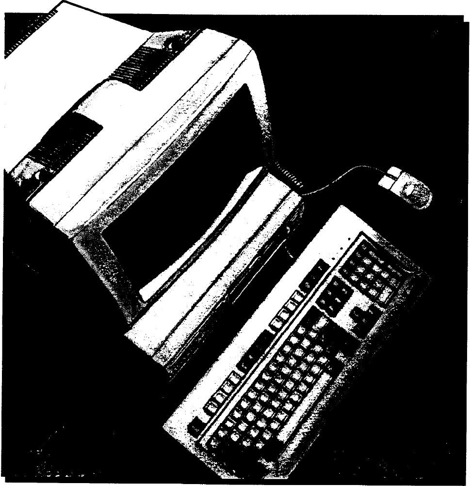
5Connecting the KeyboardTo connect the keyboard, hold the cable connector so the arrowon the connector faces up. Insert it into the port marked K/B, a
You can change the angle of the keyboard by adjusting the legson the bottom. Turn it over and flip each leg upward until itlocks into place. It is imp
To connect a mouse to the built-in mouse port, plug theconnector into the port marked MOUSE, as shown below.MOUSECautionAlthough the connectors and po
7Connecting the Power CordFollow these steps to connect the power cord:1.Plug the power cord into the AC power INLET on the backpanel, as shown below.
Turning On the ComputerAfter you set up your system, you’re ready to turn on thepower. Follow these steps:1.Turn your computer around so the front pan
4.If necessary, use the controls on your monitor to adjust thebrightness and contrast until characters on the screen areclear and at a comfortable lev
Chapter 2Running the SETUP ProgramThe first time you use your computer, you need to run theSETUP program to define how your system is set up. You mayn
The configuration you define through SETUP is stored in aspecial area of memory called CMOS RAM. This memory isbacked up by a battery, so it is not er
NoteIf you are using a monochrome monitor and are havingtrouble seeing your cursor position, press IF2) to changethe screen colors. Your cursor change
EPSON®Setup Guide@This manual is printed on recycled paper and is 100% recyclable.
Setting the Date and TimeThe real-time clock in your computer continuously tracks thedate and time-even when the computer is turned off. Onceyou set t
Setting the Video Display TypeThe Video option lets you define the type of adapter you areusing for your primary display. If you connected your monito
If you install one type of display adapter card and then changethe adapter (from VGA to CGA or vice-versa), you also mayneed to set jumper J5. If you
Setting the CacheYour computer comes with an 8KB internal memory cache builtinto the microprocessor. The SETUP program allows you todisable or enable
The Shadow options let you choose what to place in theshadow RAM area.Shadow RAM optionsSystem BIOSYou want to copy only your system BIOS into RAMVide
Setting the Password (Security) OptionsThe SETUP program lets you enter, change, or disable anoptional password to control who can access your system.
5.Enter the password you want to use. As you type thepassword, the screen displays an asterisk for each letter.Then you see this prompt:Confirm Passwo
Setting the Hard Disk Drive(s)The SETUP program lets you select the type of hard diskdrive(s) installed in your computer. If you have two hard diskdri
Hard Disk Drive TypesThe following table lists the types of standard hard disk drivesyou can use. Check this table and the documentation suppliedwith
Hard disk drive types (continued)CDC 942 16-106IIIII I- user defined -*Actual size when formatted may be slightly different than the size listed onthe
IMPORTANT NOTICEDISCLAIMER OF WARRANTYEpson America makes no representations or warranties, either express or implied, by orwith respect to anything i
Defining Your Own Drive TypeIf the parameters for your hard disk (listed in itsdocumentation) do not match any of the types listed in the tableabove,
Checking System MemoryYour computer comes with 4MB of random access memory.MS-DOS and application programs that run under MS-DOS usethe first 640KB of
If you select C , A, the computer loads the operating systemfrom drive C. If it doesn’t find the operating system on drive C,it checks the diskette in
Setting the NumLock Boot StatusThe NumLock Boot Status option allows you to select theinitial state of the num lock function when you turn on or reset
The following table lists the possible optional settings.Bus control optionsBus control optionSettingISA CommandDelayISA Wait StateI/O Recovery TimeEn
Setting the I/O Control OptionsThe I/O control options let you change the settings for thefollowing built-in interface ports:0 ParallelCl Serial 1Cl S
I/O control options (continued)1 I/O control option 1 SettingDescriptionIDE Select1 ~3-1~~11 !JrrnalharddiskDisables the internal hard diskFDC SelectE
Setting the Cache/DRAM Control OptionsYour system can use some of its reserved memory as extendedmemory and still allow shadowing of both the system a
Saving Your Settings and Exiting SETUPWhen you leave the SETUP program, you can choose to eithersave the settings you have changed or exit the program
Post-SETUP ProceduresIf you have just run SETUP for the first time and your systemhas not been configured, you now need to install the operatingsystem
Important Safety Instructions1.Read all of these instructions and save them for later reference.2.Follow all warnings and instructions marked on the c
Appendix AUsing MemoryYour computer comes with 4MB of memory, and you may haveinstalled additional memory. This appendix describes how thememory in yo
Reserved memo y is addressable memory in the range 640KB to1MB. Normally, a video card or option card must provide thephysical RAM for these addresses
For more information about your system’s memory, see the“System Memory Map” in Appendix A of the User‘s Guide.For instructions on using your memory ma
IndexAAC power inlet, 1-13Addresses, 2-19, A-1 -2Air circulation, 1-2ALE, extended, 2-18Analog connector, 1-4Application programs, 1-15,2-15 -16, 2-23
DDate, setting, 2-1, 2-4DB-9P connector, 1-9Default settings, SETUP program,booting sequence, 2-15bus control, 2-17-18cache, 2-7I/O control, 2-19-20nu
JJumper settings, 2-5-6KKeyboard,adjusting angle, 1-11cable, 1-10Connecting, 1-10 -11legs, 1-11num lock, 2-1, 2-17port, 1-10, 1-12self test error leve
PParallel port, 1-7 -8, 2-19Password, 2-1 ,2-9 -10Port,addresses, parallel 2-19built-in VGA, 1-4 -5, 2-5keyboard, 1-10, 1-12monitor, 1-4 -5,2-5mouse,
SETUP program,hard disk drive type(s), 2-1, 2-11 -14help screen, 2-3internal cache, 2-7internal drive controllers, 2-20I/O control options, 2-1, 2-19
powerhard disk(SPEED) light access lightdiskettedriveIIIhard disk or diskettedrive bayoption card slotspowerbutton
10. Do not allow the computer’s power cord to become damaged orfrayed.11. If you use an extension cord with the computer, make sure thetotal of the am
Instructions Importantes de Skuriti!1.2.3.4.5.6.7.8.9.Lire completement les instructions qui suivant et les conserverpour references futures.Bien suiv
vi
ContentsIntroductionChapter 1Setting Up Your System1 Choosing a Location.......2 Removing the Protective Card......3 Conn
Related products and manuals for Printers Epson 7500
 (4 pages)
(21 pages)
(4 pages)
(74 pages)
(11 pages)
(7 pages)
(4 pages)
(4 pages)
(4 pages)
(4 pages)
(5 pages)
(180 pages)
(281 pages)
(4 pages)
(4 pages)
(4 pages)
(21 pages)
(4 pages)
(74 pages)
(11 pages)
(7 pages)
(4 pages)
(4 pages)
(4 pages)
(4 pages)
(5 pages)
(180 pages)
(281 pages)
(4 pages)
(4 pages)
© 2020, manymanuals.com. All rights reserved. | 1.543 s |
 Manymanuals.com
 Manymanuals.de
 Manymanuals.fr
 Manymanuals.it
 Manymanuals.pl
 Manymanuals.cz
 Manymanuals.es
 Manymanuals-pt.com
Comments to this Manuals